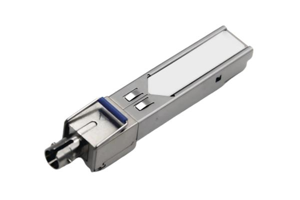
Description
This kind of Transceivers are a high performance, cost effective module which have a single ST optics interface. They are compatible with the Small Form Factor Pluggable Multi-Sourcing Agreement (MSA) and Digital diagnostics functions are available via the 2-wire serial bus specified in SFF-8472. The receiver section uses a PIN receiver and the transmitter uses a 1310 nm FP laser, up to 10dB link budge ensure this module 1000Base-SX Ethernet 550m application.
Features
- Up to 1.25Gb/s Data Links
- Hot-Pluggable Single ST connector
- Up to 550m on 50/125μm MMF
- 1310nm FP laser transmitter
- 1550nm PIN photo-detector
- Power Supply:+3.3V
- Monitoring Interface Compliant with SFF-8472
- Maximum power dissipation <1W
- Industrial /Commercial operating temperature range: -40°C to 85°C/-0°C to 70°C
- RoHS compliant and Lead Free
Applications
- 1000Base-SXEthernet
- Metro/Access Networks
- 1G Fibre Channel
- Other Optical Links
Absolute Maximum Ratings
|
Parameter
|
Symbol
|
Min.
|
Typical
|
Max.
|
Unit
|
|
Storage Temperature
|
TS
|
-40
|
-
|
+85
|
°C
|
|
Supply Voltage
|
VCC
|
0
|
-
|
+3.5
|
V
|
|
Relative Humidity
|
RH
|
0
|
-
|
85
|
%
|
|
Soldering Temperature & Time
|
|
-
|
-
|
260/10
|
℃/S
|
Recommended Operating Environment
|
Parameter
|
Symbol
|
Min.
|
Typical
|
Max.
|
Unit
|
|
Operating Temperature
|
Industrial
|
TC
|
-40
|
-
|
85
|
°C
|
|
Commercial
|
0
|
-
|
+70
|
|
Supply Voltage
|
VCC
|
3.1
|
-
|
3.5
|
V
|
|
Supply Current
|
ICC
|
-
|
-
|
200
|
mA
|
Optical Characteristics (TOP =Tc, VCC = 3.135 to 3.465 Volts)
|
Parameter
|
Symbol
|
Min.
|
Typical
|
Max.
|
Unit
|
Note
|
|
Transmitter Section:
|
|
Center Wavelength
|
λc
|
1270
|
1310
|
1350
|
nm
|
1
|
|
Spectral Width(RMS)
|
σRMS
|
-
|
-
|
4
|
nm
|
|
|
Optical Output Power
|
Pout
|
-12
|
|
-3
|
dBm
|
2
|
|
Extinction Ratio
|
ER
|
9
|
-
|
-
|
dB
|
3
|
|
Eye Mask for Optical Output
|
Compliant with IEEE802.3 z (class 1 laser safety)
|
|
|
Receiver Section:
|
|
|
Optical Input Wavelength
|
λc
|
1530
|
1550
|
1570
|
nm
|
|
|
Receiver Overload
|
PMAX
|
-3
|
-
|
-
|
dBm
|
4
|
|
RX Sensitivity
|
PMIN
|
-
|
-
|
-22
|
dBm
|
4
|
|
RX_LOS Assert
|
LOS A
|
-
|
-
|
-27
|
dBm
|
|
|
RX_LOS De-assert
|
LOS D
|
-35
|
-
|
-
|
dBm
|
|
|
General Specifications:
|
|
Data Rate
|
BR
|
-
|
1.25
|
-
|
Gb/s
|
|
|
Bit Error Rate
|
BER
|
-
|
-
|
10-12
|
|
|
|
Max. Supported Link Length on
50/125μm 该邮件地址已受到反垃圾邮件插件保护。要显示它需要在浏览器中启用 JavaScript。/s
|
LMAX
|
-
|
550
|
-
|
m
|
|
|
Total System Budget
|
LB
|
10
|
-
|
-
|
dB
|
|
Note:
- The optical power is launched into MMF.
- 20-80%.
- Contributed total jitter is calculated from DJ and RJ measurements using TJ = RJ + DJ. Contributed RJ is calculated for 1x10-12 BER by multiplying the RMS jitter (measured on a single rise or fall edge) from the oscilloscope by 14. Per FC-PI (Table 9-SM jitter output, note 1), the actual contributed RJ is allowed to increase above its limit if the actual contributed DJ decreases below its limits, as long as the component output DJ and TJ remain within their specified FC-PI maximum limits with the worst case specified component jitter input.
- Measured with PRBS 27-1 at 10-12 BER
Pin Function Description
|
Pin No
|
Name
|
Function
|
Plug Seq
|
Notes
|
|
1
|
VeeT
|
Transmitter Ground
|
1
|
1
|
|
2
|
TX Fault
|
Transmitter Fault Indication
|
3
|
|
|
3
|
TX Disable
|
Transmitter Disable
|
3
|
2
|
|
4
|
MOD-DEF2
|
Module Definition
|
2
|
3
|
|
5
|
MOD-DEF1
|
Module Definition 1
|
3
|
3
|
|
6
|
MOD-DEF0
|
Module Definition 0
|
3
|
3
|
|
7
|
Rate Select
|
Not Connected
|
3
|
4
|
|
8
|
LOS
|
Loss of Signal
|
3
|
5
|
|
9
|
VeeR
|
Receiver Ground
|
1
|
1
|
|
10
|
VeeR
|
Receiver Ground
|
1
|
1
|
|
11
|
VeeR
|
Receiver Ground
|
|
1
|
|
12
|
RD-
|
Inv. Received Data Out
|
3
|
6
|
|
13
|
RD+
|
Received Data Out
|
3
|
6
|
|
14
|
VeeR
|
Receiver Ground
|
3
|
1
|
|
15
|
VccR
|
Receiver Power
|
2
|
1
|
|
16
|
VccT
|
Transmitter Power
|
2
|
|
|
17
|
VeeT
|
Transmitter Ground
|
1
|
|
|
18
|
TD+
|
Transmit Data In
|
3
|
6
|
|
19
|
TD-
|
Inv. Transmit In
|
3
|
6
|
|
20
|
VeeT
|
Transmitter Ground
|
1
|
|
Note:
- Circuit ground is internally isolated from chassis ground.
- Laser output disabled on TDIS >2.0V or open, enabled on TDIS <0.8V.
- Should be pulled up with 4.7k - 10 kohms on host board to a voltage between 2.0V and 3.6V. MOD_DEF(0) pulls line low to indicate module is plugged in.
- Rate select is not used
- LOS is open collector output. Should be pulled up with 4.7k–10 kohms on host board to a voltage between 2.0V and 3.6V. Logic 0 indicates normal operation; logic 1 indicates loss of signal.
- AC Coupled
Mechanical Dimensions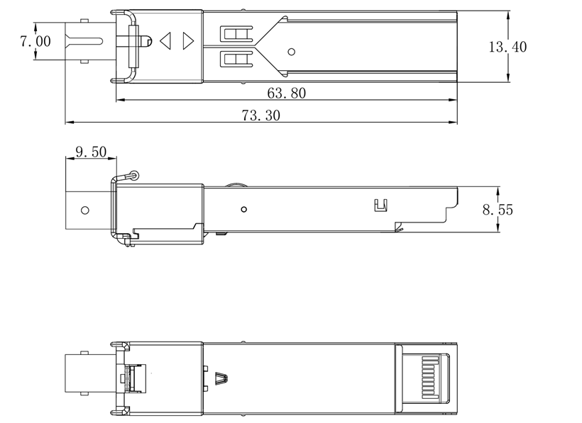
Ordering Information
|
型号
Model
|
速率
Data rate
|
激光器LD
|
波长和模式
Wavelength
and Mode
|
发射光功率
Po(dBm)
|
接收灵敏度
Sen(dBm)
|
距离Distance
|
接口
Connector
|
温度
Temp
|
|
FTCS-BM1312-02ST
|
1.25Gb/s
|
FP
|
MM1310nm
|
-12~-3
|
≤-22
|
550m
|
ST
|
-0°C to 70°C
|
|
FTCS-BM1312-02STI
|
MM1310nm
|
-40°C to 85°C
|
|
FTCS-BM1512-02ST
|
MM1550nm
|
-0°C to 70°C
|
|
FTCS-BM1512-02STI
|
MM1550nm
|
-40°C to 85°C
|
北亿纤通 | F-tone Networks